≡
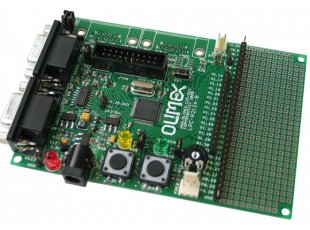
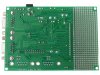
LPC-P2124
Prototype board for LPC2124 ARM7TDMI-S microcontroller
| Price | 46.95 EUR |
|---|---|
| 10 - 49 pcs | 42.26 EUR |
| 50 - 10000 pcs | 37.56 EUR |
FEATURES
- MCU: LPC2124 16/32 bit ARM7TDMI-S™ with 256K Bytes Program Flash, 16K Bytes RAM, RTC,4x 10 bit ADC 2.44 uS, 2x UARTs, I2C, SPI, 2x 32bit TIMERS, 7x CCR, 6x PWM, WDT, 5V tolerant I/O, up to 60MHz operation
- Standard JTAG connector with ARM 2x10 pin layout for programming/debugging with ARM-JTAG
- Three on board voltage regulators 1.8V, 3.3V and 5V with up to 800mA current
- Single power supply: +7-9VDC required
- Power supply status LED
- Power supply filtering capacitor
- Two channel RS232 interface with two RS232 SUB-D 9 pin connectors
- iButton interface circuit
- Frequency input connector
- Two buttons
- Two status LEDs
- Potentiometer connected to AIN
- RESET circuit with exterman control of Philips ISP utility via RS232
- RESET button
- DBG jumper for JTAG enable
- BSL jumper for bootloader enable
- JRST jumper for enable/disable external RESET vontrol by RS232
- 14.7456 Mhz crystal allow easy communication setup (4x PLL = 58,9824 Mhz CPU clock)
- Extension headers for all uC ports
- PCB: FR-4, 1.5 mm (0,062"), green soldermask, white silkscreen component print
- Dimensions: 115x80 mm (4.5x3.2")
HARDWARE
- LPC-P2124 Schematic Revision C
SOFTWARE
- RS232 initialization demo code
- Blink LED and buttons demo code
- OpenOCD + Eclipse set of projects 1.00 includes make file written in flash for LPC-P2124. The complete list of projects included is here.