- Welcome to Olimex Support Forum.
Olimex Support Forum
Recent posts
#51
A64 / Re: A64-OLinuXino-2Ge16G-IND: ...
Last post by ericstokes - June 18, 2026, 11:47:36 AMQuote from: Brati on May 18, 2026, 04:52:36 PMI am developing a Yocto 5.0 (Scarthgap) Linux image for the A64-OLinuXino-2Ge16G-IND board and have encountered a critical issue with warm reboot that I have been unable to resolve.The issue is most likely not TF-A, since BL31 successfully hands off to U-Boot at 0x4a000000. A64 warm-reset problems are often caused by SPL/DRAM/clock state not being fully reinitialized after reboot.
Issue:
The board hangs on every reboot (warm reset and cold reset) after the following boot log line:
INFO: BL31: Preparing for EL3 exit to normal world
INFO: Entry point address = 0x4a000000
INFO: SPSR = 0x3c9
[HANG - no U-Boot output]
First cold power-on always works correctly. The hang occurs every time after any reboot command.
Setup:
- Board: A64-OLinuXino-2Ge16G-IND
- U-Boot: 2024.01 (mainline, from Yocto Scarthgap / poky)
- TF-A: 2.10.4 with SUNXI_PSCI_USE_NATIVE=1 SUNXI_PSCI_USE_SCPI=1
- Crust SCP: v0.6.0 (a64-olinuxino_defconfig)
- Kernel: Linux 6.6.85
- Boot device: SD card (mmcblk0)
What I have tried:
- Added Crust SCP firmware (scp.bin embedded in U-Boot SPL)
- Added R_WDOG fix for A64 in reset_cpu() in board.c
- Added PLL6 lock timeout in clock_init_safe() in clock_sun6i.c
- TF-A rebuilt with LOG_LEVEL=40 - confirmed BL31 completes successfully and hands off to U-Boot at 0x4a000000
- U-Boot freezes before printing a single character
The hang is confirmed to be between BL31 exit and U-Boot's first UART output.
Question:
Can anyone please share which U-Boot version and if any specific patches you use in your Olimage builds for the A64-OLinuXino to make reboot work correctly?
Any guidance would be greatly appreciated.
Best regards,
Bratiranjan Acharya
bratiranjan12@gmail.com
I'd recommend testing a newer mainline U-Boot (2024.10+ or current master) or enabling CONFIG_DEBUG_UART to see how early it hangs.
#52
New Products release / Home Automation with Phone Not...
Last post by olimex - June 11, 2026, 02:46:54 PMYes, It's Possible!
How to do it with EUR 4.95 ESP32-C3-DevKit-LiPo tutorial https://olimex.wordpress.com/2026/06/11/home-automation-with-phone-notifications-for-under-e5-yes-its-possible/
#esp32 #espressif #telegram #homeautomation #iot #notifications #door #monitoring #motion #detection
How to do it with EUR 4.95 ESP32-C3-DevKit-LiPo tutorial https://olimex.wordpress.com/2026/06/11/home-automation-with-phone-notifications-for-under-e5-yes-its-possible/
#esp32 #espressif #telegram #homeautomation #iot #notifications #door #monitoring #motion #detection
#53
A13 / Re: How update nand flash of m...
Last post by colpamax - June 10, 2026, 01:01:50 PMNew script is ready! Now you can move Linux to NAND without step 4) of previous instruction. Also 7 different Android partitions are combined into nandc. After all you have 3 partitions nanda (uboot and kernel),nandb (configuration), nandc (root).
Please be patient during tar working part.
1) Install Android to NAND using LiveSuit
2) Install Debian to SD card.
3) Run Debian from SD card and run script.
All the steps are described thoroughly in previous posts.
Please be patient during tar working part.
1) Install Android to NAND using LiveSuit
2) Install Debian to SD card.
3) Run Debian from SD card and run script.
All the steps are described thoroughly in previous posts.
Code Select
#!/bin/sh

python -c '
import struct, zlib, os, sys
p = "/sys/class/block/nand/size"
if not os.path.exists(p):
    print "Error"
    sys.exit(1)
with open(p, "r") as f:
    t = int(f.read().strip())
L = [("bootloader", 2048, 32768), ("env", 34816, 4096), ("rootfs", 38912, t - 36864)]
e = ""
for idx, (n, st, sz) in enumerate(L):
    if idx == 0:
        l1 = struct.pack("<BBB5sII", 0, 0, 3, "\x00" * 5, st, 0)
    else:
        l1 = struct.pack("<QII", 0, st, 0)
    e += l1 + struct.pack("<I4sQ", sz, "DISK", 0) + n.ljust(16, "\x00") + "\x00" * 16
b = (struct.pack("<II8s", 0, 0x100, "softw311") + e).ljust(1024, "\x00")
out = ""
for i in range(4):
    c = b[:17] + struct.pack("B", i) + b[18:]
    out += struct.pack("<I", zlib.crc32(c[4:]) & 0xffffffff) + c[4:]
with open("nand_part.bin", "wb") as f:
    f.write(out)
print "Done"
'

dd if=nand_part.bin of=/dev/nand bs=1k count=4
sleep 1
sync
sleep 1
sync
sleep 1

blockdev --rereadpt /dev/nand
sleep 2
blockdev --rereadpt /dev/nand
sleep 2
blockdev --rereadpt /dev/nand
sleep 2

umount /dev/nandc
mkfs.ext4 /dev/nandc
tune2fs -o journal_data_writeback /dev/nandc
tune2fs -O ^has_journal /dev/nandc
e2fsck -f /dev/nandc


mkdir /mnt/nandroot
mount /dev/nandc /mnt/nandroot

tar --exclude=/proc/* \
    --exclude=/sys/* \
    --exclude=/dev/* \
    --exclude=/tmp/* \
    --exclude=/run/* \
    --exclude=/mnt/* \
    --exclude=/media/* \
    --exclude=/var/log/* \
    --exclude=/var/tmp/* \
    -cf - / | (cd /mnt/nandroot && tar -xf -)

cat << 'EOF' > /mnt/nandroot/etc/fstab
/dev/nandc    /              ext4    defaults,noatime,nodiratime,commit=60    0    1
tmpfs         /tmp           tmpfs   defaults,noatime,mode=1777,size=64M      0    0
tmpfs         /var/log       tmpfs   defaults,noatime,mode=0755,size=32M      0    0
tmpfs         /var/tmp       tmpfs   defaults,noatime,mode=1777,size=32M      0    0
EOF

umount  /mnt/nandroot
rmdir /mnt/nandroot


mkdir -p /mnt/sdboot
mount /dev/mmcblk0p1 /mnt/sdboot

mkdir -p /mnt/nandboot
mount /dev/nanda /mnt/nandboot

cp /mnt/sdboot/uImage /mnt/nandboot/
cp /mnt/sdboot/script.bin /mnt/nandboot/
umount /mnt/sdboot
rmdir /mnt/sdboot
umount /mnt/nandboot
rmdir /mnt/nandboot


cat << 'EOF' > u-boot.txt
baudrate=115200
bootdelay=1
console=ttyS0,115200
loglevel=8
machid=102a
nand_root=/dev/nandc
init=/sbin/init
setargs=setenv bootargs console=${console} root=${nand_root} rootwait init=${init} loglevel=${loglevel}
boot_normal=fatload nand 0:0 0x44000000 uImage; bootm 0x44000000
bootcmd=run setargs boot_normal
EOF


python -c "
import zlib, struct
with open('u-boot.txt', 'r') as f:
    lines = [line.strip() for line in f if line.strip()]
data = '\x00'.join(lines) + '\x00'
target_size = 131072 - 4
data = data.ljust(target_size, '\x00')
crc = zlib.crc32(data) & 0xffffffff
header = struct.pack('<I', crc)
with open('env.bin', 'wb') as f:
    f.write(header + data)
print('env.bin reafy! filesize:', len(header + data))
"
sudo dd if=env.bin of=/dev/nandb bs=1k
sync

rm env.bin u-boot.txt

echo "All done! Now power off the board, remove SD card and next time it will boot Linux from NAND!"
#54
FPGA / Re: First time issues programm...
Last post by LubOlimex - June 10, 2026, 09:15:26 AMThanks for the feedback and the repo, I will make sure to link at the product page, under "Community".
#55
FPGA / Re: First time issues programm...
Last post by nachoworks - June 09, 2026, 09:53:35 PMTo make up for the critique of my last comment, I thought I'd help out:
Enjoy fellow travellers! https://github.com/kerstensrobin/iCE40HX1k-EVB-exploration
Scraping together some documentations and clarifying things that were not necessarily clear to me in the beginning, being out of practice when it comes to FGPA development.
Enjoy fellow travellers! https://github.com/kerstensrobin/iCE40HX1k-EVB-exploration
Scraping together some documentations and clarifying things that were not necessarily clear to me in the beginning, being out of practice when it comes to FGPA development.
#56
FPGA / First time issues programming ...
Last post by nachoworks - June 09, 2026, 12:26:58 PMI did not find a similar topic, but wanted to share this information to avoid other people bumping into the same issue  I spent about two nights trying to program the iCE40HX1K-EVB using my RPi 4 with no success, checking connections, switching pins on the RPi.
Dear fellow FPGA-traveller: The PGM-1 connector does not have pin 1 in the top left corner!

In the documentation and schematics this is rotated 180 degrees
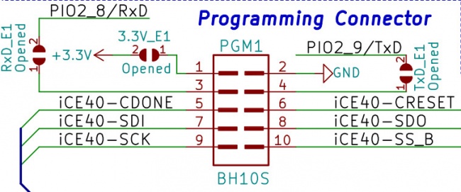
The average reader: "PCB layout does not follow the schematic!!!"
I know, pebkac, this is probably due to my own experience in placing pin1 always in the same orientation on schematic/board.
I just wanted to have this highlighted somewhere
Also: the documentation for this board is somewhat outdated as it mentions RPi2's and some dead links at the bottom when it comes to RPi programming.
I spent about two nights trying to program the iCE40HX1K-EVB using my RPi 4 with no success, checking connections, switching pins on the RPi.Dear fellow FPGA-traveller: The PGM-1 connector does not have pin 1 in the top left corner!
In the documentation and schematics this is rotated 180 degrees
The average reader: "PCB layout does not follow the schematic!!!"
I know, pebkac, this is probably due to my own experience in placing pin1 always in the same orientation on schematic/board.
I just wanted to have this highlighted somewhere
Also: the documentation for this board is somewhat outdated as it mentions RPi2's and some dead links at the bottom when it comes to RPi programming.
#57
A64 / Re: Debian GNU/Linux 13 (Trixi...
Last post by mossroy - June 07, 2026, 09:58:51 AMQuote from: Roman on June 06, 2026, 08:09:08 PMCould you tell which revisions of the board you have?
All my A64 boards are A64-OLinuXino-2Ge8G-IND rev E
#58
A64 / Re: Debian GNU/Linux 13 (Trixi...
Last post by Roman - June 06, 2026, 08:09:08 PMQuote from: mossroy on May 14, 2026, 10:36:02 PMI've described a different procedure to install Debian 13 on my A64-OLinuXino-2Ge8G-IND boards: https://blog.mossroy.fr/2026/05/14/debian-13-sur-a64-olinuxino-2ge8g-ind/ (it's written in French).
Thank you for sharing. Could you tell which revisions of the board you have?
By the way, my attempt above was successful too.
Quote from: Roman on May 10, 2026, 09:05:36 PMNow it boots as expected untill "Starting kernel ..."
I had to switch to HDMI and append the Linux arguments with "console=tty1" as suggested in the first post in this thread. I set it in boot.scr, which required rebuilding boot.scr with mkimage. The resulting installation boots, gives HDMI output, and has Internet access.
I did not look into applying the overlay again. Apparently, it can be done. But I would rather see the issue fixed in the upstream.
The serial output keeps failing, but that is another issue.
Code Select
[ 2.836347] gpio gpiochip0: Static allocation of GPIO base is deprecated, use dynamic allocation.
[ 2.847404] sun50i-a64-r-pinctrl 1f02c00.pinctrl: initialized sunXi PIO driver
[ 2.856795] sun50i-a64-r-pinctrl 1f02c00.pinctrl: supply vcc-pl not found, using dummy regulator
[ 2.866685] sunxi-rsb 1f03400.rsb: RSB running at 4000000 Hz
[ 2.877472] gpio gpiochip1: Static allocation of GPIO base is deprecated, use dynamic allocation.
[ 2.891691] sun50i-a64-pinctrl 1c20800.pinctrl: initialized sunXi PIO driver
[ 2.900359] dw-apb-uart 1c28000.serial: Error applying setting, reverse things back
[ 2.909301] dw-apb-uart 1c28000.serial: Error applying setting, reverse things back
[ 2.981557] clk: Disabling unused clocks
#59
ESP32 / Re: I built an 8-bit Retro Aud...
Last post by UfkuAcik - June 05, 2026, 12:31:46 PMThank you very much. Please upload the code to the board and test it out when you have the time. It is particularly important to me that the DSP block meets expectations, so I am very curious to hear your thoughts on this point.
As a quick note, I plan to include the following features in the project in the future:
Remastering the algorithms in the DSP block to ensure full academic compliance and optimizing the related functions to the highest possible degree.
The ability to import short external audio files (1-2 seconds) from an SD card into the synthesizers (signal generators) and synchronize them to the tempo.
Real-time recording from the master output to the SD card during runtime.
Improvements to make it impossible for the master audio output to clip/distort, even as a result of heavy effects and boosting.
#60
A13 / Re: How update nand flash of m...
Last post by colpamax - June 05, 2026, 12:28:46 PMAndroid partitioning remains unchanged.
Debian root partition is installed in biggest nandi (around 2.6 Gb)
Debian Home partition is installed in nandd (around 512 Mb)
2 smaller partitions (256Mb each) are mounted as 'storage' and 'backup' under 'mnt' folder. Use them for your files as you wish.
One more Android 128Mb partition is mounted automatically by XFCE. You can delete Android files from it and use for your needs.
May be for another Android images (for example for 8Gb NAND) script must be changed.
I can't check this.